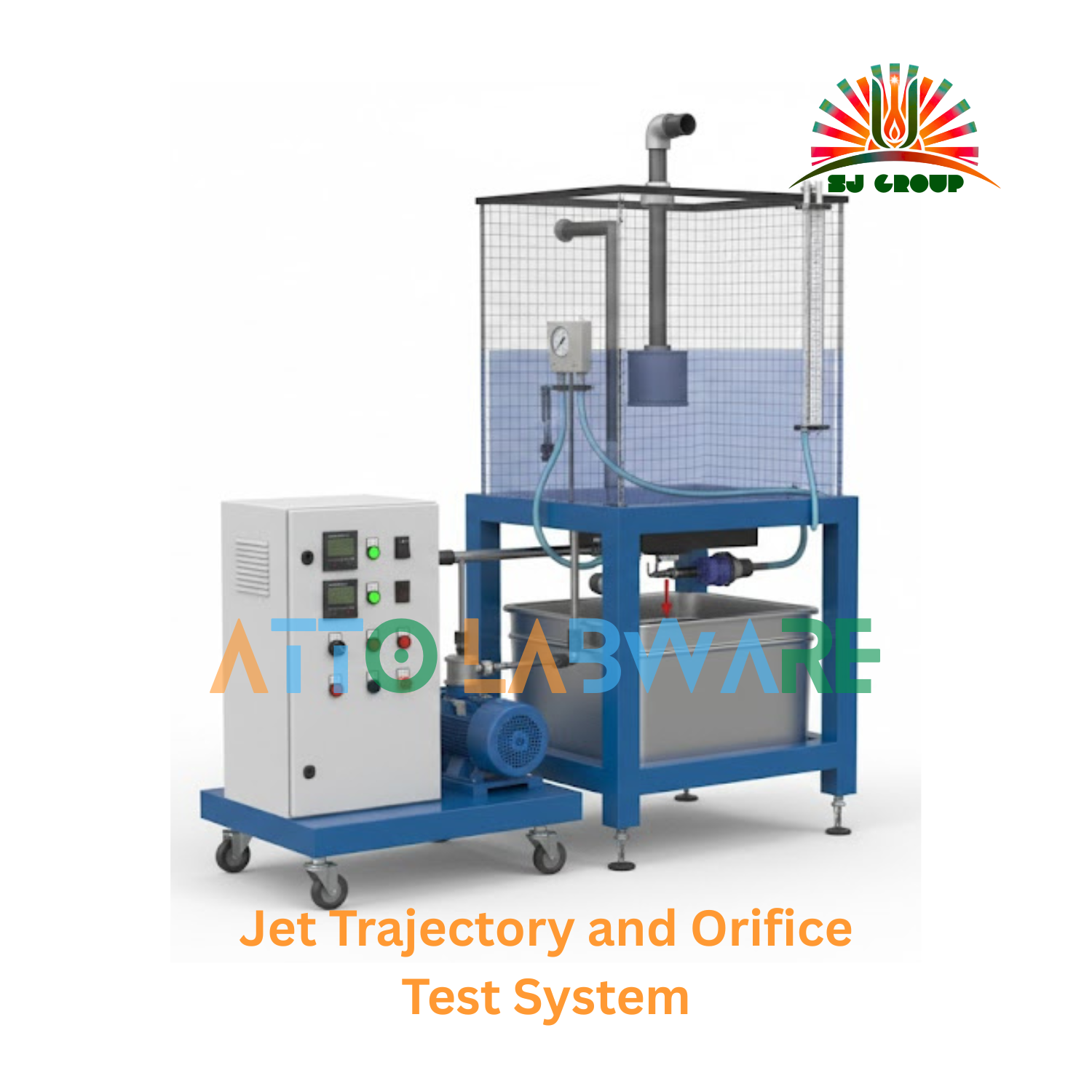
Jet Trajectory and Orifice Test System
The Jet Trajectory and Orifice Test System by Atto Labware is designed to study the discharge characteristics of orifices and the trajectory of a free jet under gravity. It enables students to verify the theoretical equations of jet motion, calculate the coefficient of discharge, and visualize the parabolic path of a fluid jet. This apparatus provides hands-on understanding of fluid mechanics principles related to jet velocity, energy conversion, and projectile motion of liquids.
Educational Objectives
Students and researchers will be able to:
-
Determine the coefficient of discharge, velocity, and contraction for a given orifice.
-
Measure and analyze the trajectory of a water jet under gravity.
-
Verify theoretical equations for projectile motion of a jet.
-
Study the effect of head and orifice size on jet trajectory.
-
Understand the energy conversion from potential to kinetic form in a free jet.
Performance Measurement
-
Measurement of jet trajectory coordinates (horizontal and vertical displacements).
-
Determination of discharge rate through the orifice.
-
Calculation of velocity coefficient and discharge coefficient.
-
Comparison of experimental results with theoretical parabolic paths.
-
Observation of jet behavior for different orifice diameters.
Panel and Instruments / Components
-
Transparent Tank: Cylindrical acrylic tank fitted with an interchangeable orifice plate.
-
Orifice Set: Includes multiple brass orifices of varying diameters (typically 3–10 mm).
-
Coordinate Measuring Grid: Graduated transparent grid for measuring jet path coordinates.
-
Flow Control Valve: For precise adjustment of the water head.
-
Head Measurement Scale: Mounted scale for accurate water level measurement.
-
Water Supply System: Operates with a hydraulic bench or recirculating pump.
-
Collection Tank: For measuring discharge volume over time.
-
Support Frame: Powder-coated steel frame with anti-corrosive fittings.
Specifications (Includes Technical Data)
| Feature | Detail |
|---|---|
| Orifice Diameters | 3 mm, 6 mm, 9 mm (interchangeable) |
| Tank Diameter | 300 mm (clear acrylic) |
| Water Head Range | 0 – 500 mm |
| Coordinate Grid | Graduated 1 mm divisions |
| Working Fluid | Water |
| Flow Control | Needle valve with fine adjustment |
| Measuring Tank Capacity | 20 L |
| Operating Temperature | +5 °C to +40 °C |
| Storage Temperature | –25 °C to +55 °C |
| Construction | Transparent acrylic tank with stainless steel fittings |
| Dimensions | 600 mm L × 400 mm W × 800 mm H |
| Weight (Approx.) | 15 kg |
Note: Digital measuring scale, flow sensors, and data acquisition systems available on request