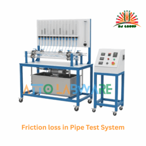

Pipe Friction Losses Test System
The Pipe Friction Losses Test System is a precision-engineered educational apparatus designed to demonstrate head loss due to friction in pipes under laminar and turbulent flow conditions. The system enables students to experimentally determine the friction factor, study the transition between laminar and turbulent regimes, and validate fundamental fluid mechanics theories such as Poiseuille’s law.
This unit is ideal for Civil, Mechanical, and Aerospace Engineering laboratories and can be operated independently or in conjunction with a hydraulic bench for recirculating flow.
Educational Objectives
Students and researchers will be able to:
-
Determine the relationship between head loss and flow rate in laminar and turbulent flow.
-
Identify the critical Reynolds number marking the transition between flow regimes.
-
Experimentally determine the friction factor and compare it with theoretical and Moody chart values.
-
Validate Poiseuille’s law for laminar flow.
-
Understand the effects of pipe diameter, length, and surface roughness on friction losses.
Performance Measurement
-
Measurement of differential head (pressure drop) between two pressure tapping points along the test pipe.
-
Measurement of flow rate using a volumetric method or hydraulic bench.
-
Calculation of Reynolds number and friction factor for various flow rates.
-
Observation of the transition point from laminar to turbulent flow.
-
Temperature measurement of working fluid for viscosity correction.
Panel and Instruments / Components
-
Test Pipe: Straight, smooth-bore pipe mounted horizontally with precision pressure tapping’s.
-
Manometer/Pressure Gauge: For measurement of pressure difference between upstream and downstream points.
-
Flow Control Valve: Fine needle valve for accurate regulation of flow rate.
-
Header Tank: Ensures steady flow supply during experiments.
-
Thermometer: Measures water temperature for viscosity calculations.
-
Base Frame: Powder-coated steel structure suitable for bench mounting.
-
Measuring Vessel: Provided for volumetric determination of discharge.
Specifications (Includes Technical Data)
| Feature | Detail |
|---|---|
| Test Pipe Internal Diameter | 3 mm (nominal) |
| Pipe Length | 1 m (typical) |
| Working Fluid | Water |
| Flow Rate Range | 0 – 5 L/min (typical, depending on supply) |
| Pressure Measurement Range | 0 – 530 mm water column (manometer) |
| Differential Pressure Meter Range | 0 – 20 m water |
| Operating Temperature | +5 °C to +40 °C |
| Storage Temperature | –25 °C to +55 °C |
| Overall Dimensions (Main Unit) | 1000 mm L × 840 mm H × 240 mm W |
| Weight (Approx.) | 6 kg (main unit), 5 kg (header tank) |
| Construction | Rigid steel frame with transparent manometer tubes and stainless-steel piping |
| Power Requirement | Not required (gravity or hydraulic bench feed) |
Note: Customized pipe diameters, materials, and digital sensors for data acquisition are available on request.